
Description
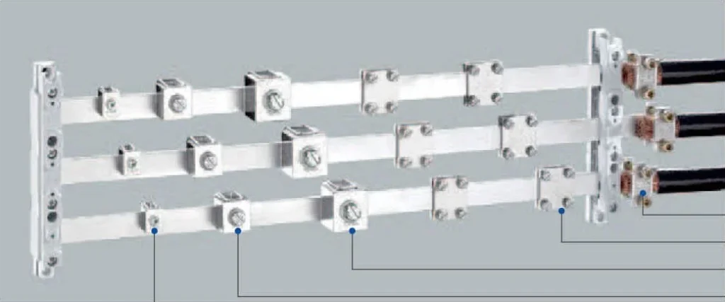
The CWNE busbar system carries the current inside a low-voltage assembly: the supports and partitions hold the copper bars at the correct pitch, insulate the phases and take the electrodynamic forces, while the bars distribute current to the outgoing devices.
What the system contains
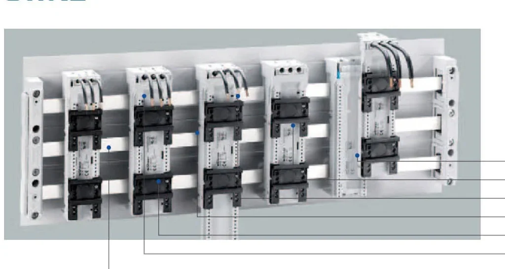
- Busbar supports in 1-line and 3-line versions for the 2T, 3T and TCC profiles, with internal thread holes for direct mounting.
- Partitions and end caps for phase separation, protection against accidental contact and completion of the bar ends.
- Copper busbars in 2T 500 mm², 2T 720 mm², 3T 1140 mm² and TCC 1600 mm², tinned or bare, in standard lengths from 453 mm to 3600 mm.
Technical data
| Parameter | Range / value |
|---|---|
| Bar profiles | 2T 500 mm² / 2T 720 mm² / 3T 1140 mm² / TCC 1600 mm² |
| Bar finish | Tinned or bare copper |
| Standard bar lengths | 453 / 492 / 590 / 650 / 653 / 692 / 790 / 2400 / 3600 mm (by profile) |
| Support versions | 1-line (single mounting) and 3-line (with internal thread holes) |
| Support material | Flame-retardant insulating moulding |
| Installation | Horizontal, inside low-voltage switchgear assemblies |
| Design standard | IEC 61439-1 / IEC 61439-2 (DIN EN 61439) |
| Pollution degree | 3 (2 in special cases) |
| Ambient reference | Published data valid at the recommended installation position and stated ambient |
How the parts work together
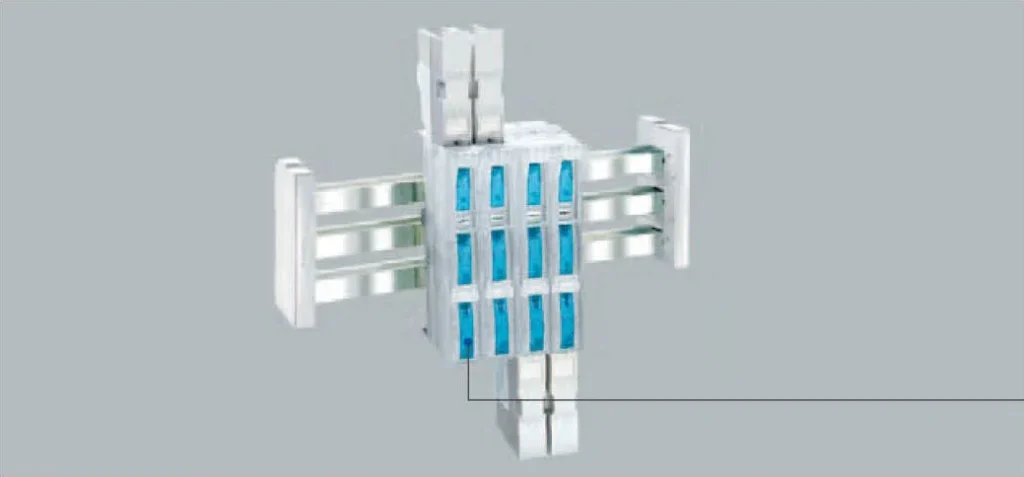
A three-line support holds the three phase bars at a fixed pitch, which keeps the electromagnetic forces balanced under short-circuit conditions. The same support accepts the end caps and the partitions, so the bar run stays insulated and touch-protected along its full length. Tap-off terminals and NH fuse switch disconnectors mount directly onto the bars, which is why the support pitch is chosen together with the tap-off plan.
Selection notes
- Choose the bar profile from the design current after applying the rated diversity factor (0.9 for 2 to 3 main circuits, 0.8 for 4 to 5, 0.7 for 6 to 9, 0.6 for 10 or more).
- Support pitch follows the short-circuit withstand required and the bar weight; three-phase bars are supported at the same pitch.
- State the bar length from the assembly layout rather than cutting on site, so the tinned surface stays intact.
Ordering information
Send the assembly type, design current, number of main circuits, busbar length and the tap-off method. Bars, supports, partitions and end caps are quoted as one schedule so the quantities match.
FAQ
Which busbar profiles are available?
2T bars in 500 mm² and 720 mm², 3T bars in 1140 mm² and TCC bars in 1600 mm², in tinned or bare copper.
What is the difference between a 1-line and a 3-line support?
A 1-line support carries a single bar run and can be mounted on its own. A 3-line support carries the three phase bars at a fixed pitch and has internal thread holes for direct mounting in the assembly.
Can the busbar be cut on site?
Bars can be cut, but the cut face must be treated to restore corrosion protection. Ordering the standard length from the layout keeps the tinned surface intact.
Which standard does the system follow?
The system is designed for low-voltage switchgear assemblies to IEC 61439-1 and IEC 61439-2 (DIN EN 61439), with a pollution degree of 3 unless otherwise agreed.
Request Quote
Tell us your specifications, quantity, or application scenario and we will reply with a tailored quote.