Rated diversity factor, taken into account
The current a busbar actually carries is lower than the sum of the outgoing ratings. We publish the diversity factor used for the system so the bar and the supports are sized for the real load:
| Main circuits | Rated diversity factor |
|---|
| 2 and 3 | 0.9 |
| 4 and 5 | 0.8 |
| 6 to 9 | 0.7 |
| 10 and above | 0.6 |
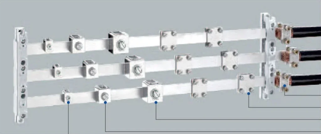
Copper conductors from 0.75 to 300 mm²
Connection terminals are rated for copper conductors from 0.75 mm² (18 AWG) to 300 mm² (600 MCM), with multi-strand conductors sized so that the current-carrying capacity is not reduced by the terminal. Tightening torques are stated per terminal and must be held to ±20 %.
Conditions of installation
Unless otherwise agreed, the published data applies to horizontal installation at the recommended position, with a pollution degree of 3 (2 in special cases) according to IEC 61439-1/-2. Where the ambient conditions differ — altitude, temperature inside the enclosure, ventilation, enclosure type — derating factors must be applied.
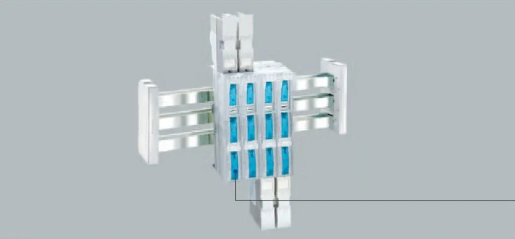
NH fuse switch disconnectors on the bar
NH fuse switch disconnectors are operated according to IEC 60269-2 and VDE 0105-100: only by qualified electrical personnel, with the switch open before a fuse is changed, and with the cover closed during operation.
Four decisions define the system: the current to be carried, the bar profile, the support arrangement and the tap-off method. Work through them in this order.
1. Establish the design current
Take the sum of the outgoing circuit ratings, apply the rated diversity factor for the number of main circuits, then correct for the ambient temperature inside the enclosure. The result is the current the bar must carry continuously — not the nominal rating of the incoming device.
2. Choose the bar profile
- 2T — 500 or 720 mm²: the general-purpose profile for distribution assemblies and panel building.
- 3T — 1140 mm²: for higher current main busbars where a 2T bar would need parallel runs.
- TCC — 1600 mm²: for main incoming sections of large assemblies.
- Multi-layer bars — 400 to 1000 mm²: where a compact, stacked run is needed; the published current ratings are 1053 A to 2110 A.
3. Fix the support arrangement
Supports are available in 1-line and 3-line versions for each bar profile, with end caps and partitions. Support spacing is chosen from the short-circuit strength required and the bar weight; three-phase bars are supported at the same pitch so the electromagnetic forces stay balanced.
4. Select the tap-off and protection
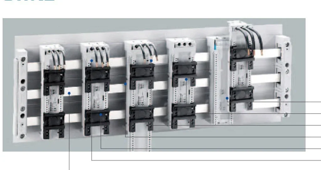
Use screw terminals for cable outgoing ways up to 300 mm², plate clamps where two cables land on the same point, and modular distribution blocks for dense single-phase tap-offs. Where a group of feeders must be fuse-protected, mount NH fuse switch disconnectors directly on the bar.
What to send for a quotation
- Design current per section and number of main circuits
- Bar profile preference (2T / 3T / TCC / multi-layer) or the assembly type
- Busbar length and support pitch, or the enclosure dimensions
- Tap-off method, cable sizes and the number of outgoing ways
- Whether NH fuse switch disconnectors or current transformers are required
- Quantity and delivery destination